Due to the virus issues, the PCB took a while to manufacture. I picked a green solder mask as this is the default colour and it normally will be manufactured in 2 days, vs. 4-7 days for a white solder mask:
- Cat-Buzzer-Toy.jpg (42.4 KiB) Viewed 14668 times
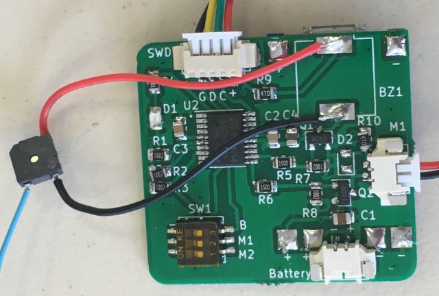
Underneath the PCB is a USB LiPo battery charger PCB. This is soldered onto my PCB using copper wire - you can see the square connection pads on the right hand side. While the board does work, the vibration motor only just turns over at the battery 3.2-3.8 voltage. While I am still waiting on the correct buzzer, the substitute buzzer faintly sounds.
I have had a re-think on the project and have instead moved to use a small 5V USB battery charger to power the board. I have removed the underside LiPo charger PCB as it's no longer needed. Next time I am in Shenzhen, I will test a number of small vibration motors to make sure they run ok at 3V range. I was hoping to put the PCB to sleep, but I think this will cause the 5V USB battery charger to drop the power supply as well, as there wont be enough current being drawn. As I write this, the next version is already on it's way to Busselton.
For people interested in a bit more info on the project, the top SWD 4 wire plug is the STM32 Software Programming/Debug port. The right hand side M1 plug is the vibration motor plug and the bottom plug is for the 3.2V Battery plug. You can just see the small micro USB plug poking out at the top right hand side (underneath the buzzer pad).
