Ok, the mag sensor didn't make it onto the next design version, but I did add a voltage divider that measures the voltage on the RGB LED string. If the MOSFET sending power to the LED string is switched off, then I should read 0 volts on the RGB LED string, but low and behold, I still measure a reduced voltage, from memory it might have been 2.4V!! How is this. VCC has 0V being sent onto it, but there is still a considerable voltage on the LED string?
I think it might be the data voltage being leaked up to VCC? Regardless, it's not 3.3V, so on the v2.2 PCB design, I added a 100k-100k voltage divider across the VCC line. I can check if there is a 3.3V or 5V voltage on the line before I switch the PCB USB 5V onto the RGB LED VCC line. Using the USB 5V would enable up to 25 odd LEDs at full brightness, or more it partial brightness.
Playing around with a variable resistor inline with the photo-transistor, I found I needed a 100K ohm resistor to give enough sensitivity to measure low levels of light and contrast against bright light. All in all, it works well and I am happy with it.
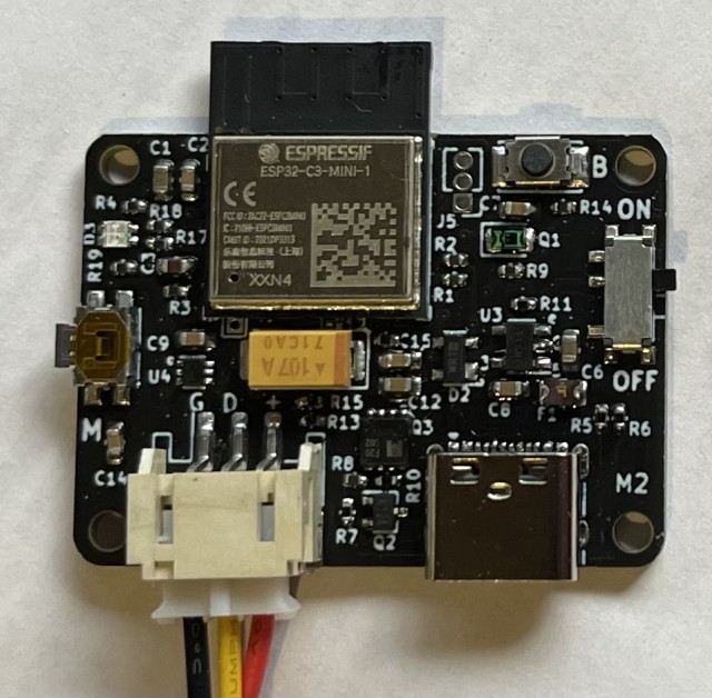
- RGB_LED-Controller_v2.2.jpg (107.57 KiB) Viewed 18009 times
Now this is only a two layer PCB, so it relatively cheap to panelise and make up. There is a tiny bit of PCB real estate left and a spare ADC1 pin available, but I would need to bump up to 4 layers to fit the magnetic sensor onto the board. Maybe one day.