X27.168 Low Power Stepper Motor

Tell us about your projects. Update us regularly.
Post Reply
parkview
Guru Maker
Posts: 603
Joined: Tue Jun 24, 2014 8:25 pm
Location: Busselton
Contact:

X27.168 Low Power Stepper Motor

Post by parkview » Thu Oct 28, 2021 9:30 pm

Back in early October 2021, Stephen put me onto a rather nifty little Stepper Motor, behold the: X27.168.
X27.1-front.jpg
X27.1-front.jpg (31.63 KiB) Viewed 9645 times
and the backside, with the two coil connectors:
X27.1-back.jpg
X27.1-back.jpg (22.89 KiB) Viewed 9645 times
It's about 30mm across and about 9mm tall. The spindle can rotate reputably at 600 degrees/second at 5V and drawing around 22mA. As you can imagine, there is little to no torque, and only good at driving an indicator needle. These stepping motors are used in a few car dash indicator dials.

There isn't much info available out there, however a kind person has written an Arduino driver software and collected datasheets etc (https://github.com/clearwater/SwitecX25), so that's a handy kick off to my project. You can buy these from Aliexpress and a controller IC, the: AX1201728, which is a replacement for the: X12.017 controller IC. This IC can drive up to four X27.168 stepper motors. You can reportable drive the stepper motor directly from a 5V based ATMEGA, like the Nano or Uno.
X27-controller.jpg
X27-controller.jpg (11.94 KiB) Viewed 9645 times
My stepper motors and controller IC's arrived this week, so I immediately created a CAD model in Design Spark Mechanical, exported it as a OBJ file, and then used FreeCAD to turn that into a nice STEP file suitable for importing into KiCAD (See: viewtopic.php?f=12&t=2427). I then created a KiCAD footprint for the stepper motor and created a simple single motor PCB and uploaded it to JLCPCB for manufacture. Here it is as a KiCAD model:
X27_PCB.jpg
X27_PCB.jpg (15.14 KiB) Viewed 9645 times
The Chinese version of the X28.168 motor is not quite physically up to spec, compared with the X27 datasheet I found online, but it should (hopefully), fit the PCB I designed up for it.
Last edited by parkview on Fri Oct 29, 2021 8:27 am, edited 2 times in total.

parkview
Guru Maker
Posts: 603
Joined: Tue Jun 24, 2014 8:25 pm
Location: Busselton
Contact:

Re: X27.168 Low Power Stepper Motor

Post by parkview » Thu Oct 28, 2021 10:01 pm

So, with the motor mount PCB off being manufactured, it's time to ponder making a controller PCB to connect to the motor PCB's. My thinking at the moment is to have the AX1201728 IC being controlled by a cheap MCU that will be incorporated on the controller PCB. The MCU will act as an i2C slave device, so essentially it will publish a list of 'Registers' to the master MCU. For example, some of these might be:

1) a register for each of the four motors that will set it's position
2) a register that for each motor that contains a 'Default' initial position. Powering on the controller, or resetting the motor will set the motor to this position.
3) one register that by setting a bit, will reset the corresponding motor back to a default position.

This is 2021 - with the world being impacted by a shortage of silicon and this also effects the MCU market.

Initially I was going to use a ESP8266 12F module, or it's replacement, the ESP32-C3. However, I need more pins than they have available, but they are cheep and available.

I would love to do another project with a STM32 MCU, however, it's practicably unobtainium, or well out my my price range for this project.

For an ATMEGA328 MCU, LCSC only have them in the humongous DIP through hole for factor. Far to large for this project, but they are around US$2 to US$3. Oh, and you would need a crystal and a large programming port for it.

That leaves the ESP32-Pico-D4 MCU thats around 7x7mm in size and incorporates a crystal and flash etc. and is only US$3.61 and has built in WiFi (when used with a Chip Antenna). Way over powered for what it's going to do, but I do have a few in stock, and LCSC have over 10K in stock.

It didn't take long to whip up a quick schematic and then a long day to place and route out the components. It's a four layer PCB, as it includes my first attempt at using a WiFi chip antenna, the AN9520:
X27_controller.1.jpg
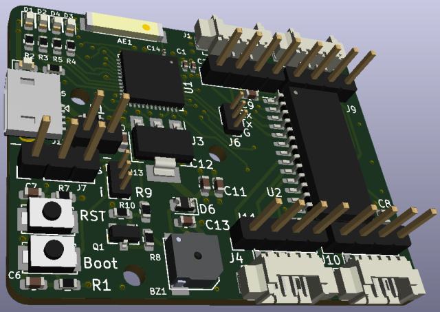
X27_controller.1.jpg (51.55 KiB) Viewed 9593 times
I find it very handy when debuging a PCB, to have all the programming info at my finger tips, so I have placed all the GPIO info on the backside:
X27_controller.2.jpg
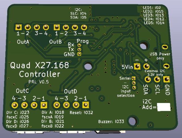
X27_controller.2.jpg (55.07 KiB) Viewed 9644 times
It's not the prettiest board and it would have helped to make the 46mm x 36mm PCB a bit larger so it had more room for clearer documentation etc. But this is the first Beta version of the board, so I am just happy if I can boot it up and program it to work.

parkview
Guru Maker
Posts: 603
Joined: Tue Jun 24, 2014 8:25 pm
Location: Busselton
Contact:

Re: X27.168 Low Power Stepper Motor

Post by parkview » Tue Nov 23, 2021 11:37 am

The controller PCB arrived the other day. I laser cut a paste solder stencil out and made up the PCB. It turned out rather well:
controller_sml.jpg
controller_sml.jpg (65.35 KiB) Viewed 9490 times
Above, I am testing out the software. My first version based on my understanding of the datasheet it didn't turn out well. It says the Max Frequency is 1.1MHz, or 7.2KHz for 600 degrees/second movement. I tried setting a ESP32-Pico PWM clock at 1.2KHz with a 50% duty cycle and got no movement.

I ended up following the code here: https://guy.carpenter.id.au/gaugette/20 ... ver-tests/ which is just bit-banging the pules out to the controller IC. Good enough for the moment.

Only two design errors with the PCB. 1) the buzzer is wired wrong, but fixed with some thin wire. 2) One datasheet note I missed was a power up timing sequence, in that the controller IC needs to be kept low for the first 100nSec . They recommend the reset line to be pulled low, so it was easy to retro-add one to the PCB.

parkview
Guru Maker
Posts: 603
Joined: Tue Jun 24, 2014 8:25 pm
Location: Busselton
Contact:

Re: X27.168 Low Power Stepper Motor

Post by parkview » Tue Nov 23, 2021 10:25 pm

So my ESP32 Arduino program was using the ledcWrite() function to output 1.2KHz PWM at a 50% duty cycle. There was nothing listed in the datasheet about maximum pulse length, only the that it had to be at least 450nSec. At 1200Hz with a 50% duty cycle, my negative going pulse was something like 417uSec long - nearly 1000 times longer than the minimum. Anyway, I found that if I adjusted the duty cycle to 99%, then it started to work.

Thanks to StephenE, for recommending me to examine circuitry using a logic analyser. I have a cheap Chinese 8 port probe and have installed PulseView to record the sessions:
pulseview.jpg
pulseview.jpg (26.87 KiB) Viewed 9486 times

Much easier to decode and measure waveforms and more precise than a oscilloscope, at least in analysing logic waveforms.
logic.sml.jpg
logic.sml.jpg (54.98 KiB) Viewed 9486 times

parkview
Guru Maker
Posts: 603
Joined: Tue Jun 24, 2014 8:25 pm
Location: Busselton
Contact:

Re: X27.168 Low Power Stepper Motor

Post by parkview » Thu Nov 25, 2021 9:22 pm

One thing I noticed playing around with ESP32 PWM channels is that they seem to effect each other. I noticed this when I set a 4KHz on channel 0 for the on board buzzer. I played a the tone, then set a 1KHz PWM frequency on channel 1. The motors move ok (now), but when I played the buzzer tone again, it was now 1KHz. Reading the docs, it sounds like there should at least be a bank of 0-7 channels on the high side timers and channels 8-15 for the low side timers.

But no, it's apparently worse than that. There are only 4 timers on each bank of 8 channels:
timer-matrix.jpg
timer-matrix.jpg (32.11 KiB) Viewed 9467 times
(from chapter 14.2: https://www.espressif.com/sites/default ... ual_en.pdf)

Which is why when I set the 1KHz tone on channel 1, it also fed that into my channel 0 buzzer. I wonder what the PWM restrictions are on a STM32 MCU?
buzzer.jpg
buzzer.jpg (79.96 KiB) Viewed 9469 times
This small buzzer (LH side), is only 5.2mm x 5.2mm and is the smallest and cheapest mag buzzer I can find (so far). It's not as loud as a piezo buzzer, but it's loud enough for my purposes, and more importantly, it's small. The resonant frequency is 4KHz, however it kind of works ok at other frequencies as well:
buzzer-freq.jpg
buzzer-freq.jpg (17.17 KiB) Viewed 9469 times

Oh, and if you look carefully, you will see the 0.1mm thin bodge fix wire skirting around the buzzer to the correct pad.

parkview
Guru Maker
Posts: 603
Joined: Tue Jun 24, 2014 8:25 pm
Location: Busselton
Contact:

Re: X27.168 Low Power Stepper Motor

Post by parkview » Tue Feb 08, 2022 2:23 pm

I like the look of this board, it's so symmetrical. I spun out a new version V1.0, to fix the buzzer and add in a IC reset pull down resistor. It also allowed me to add a +3.3V pin to the i2C Slave data port, so it can be run from 3.3V, and/or 5V as well. I also enlarged the i2C address (white space) graphic on the back to give more space to write on the i2C address that might be programmed into it.
X27 Motor Controller V1.0.jpg
X27 Motor Controller V1.0.jpg (59.89 KiB) Viewed 9043 times
I programmed this board via my new hand held external 1.27mm pogo pin adapter. This worked a treat and I am very happy with it. It saves me having to solder on a 1.27mm pinheader and I can always use the red pogo pin jig if I want a longer term connection while debugging etc.

If I do another version of this board, I would replace the AMS1117 LDO, with a MUCH smaller NCP167BMX330TBG as it's only 1mm x 1mm in size. I now realise that the i2C pin header pins could be re-arranged to allow a small OLED screen to be plugged in. As it stands currently, you would need to make up an adapter cable before using it.

Post Reply