Open-PyroJet a 3D Metal/Ceramic Printer

Tell us about your projects. Update us regularly.
Post Reply
parkview
Guru Maker
Posts: 603
Joined: Tue Jun 24, 2014 8:25 pm
Location: Busselton
Contact:

Open-PyroJet a 3D Metal/Ceramic Printer

Post by parkview » Sun Mar 27, 2022 11:50 am

On the Espressif Discord channel a few weeks ago there was an announcement by Michael, the originator of a project that is attempting to build a cheap Open Hardware based 3D printer that can print out metal and ceramics etc. As of today, there are people from USA, Europe and Australia helping out on the project. You can find out more Project information here: https://github.com/Sindry-Manufacturing Michael has been at this for a number of years, exploring different nozzle heater technologies and printhead designs., so there is quite a bit of info in the repository. Reach out to me personally if you want to join the Discord project discussions.

The basis of the tech, is that we suspend micron sized metal or ceramic particles in a naptha (I believe it's called Shellite here in oz) based fuel. A Silicon Carbide 0.135mm dia. filament is heated up, over the top of a tiny chamber 0.6mm x 1.6mm. A pulse of current vaporizes the fuel and pushes it out of the nozzle, the hot fuel explodes, melting the suspended micro particles. The molten particulates are then deposited on a substrate thats placed 0.3mm below the nozzle.

Ideally, I would like to be able to use the Open PyroJet 3D printer, to build my own ceramic based multi-layer PCB. Fuse layers of ceramic, with maybe silver traces, with blind PCB via's etc. Once finished, I could then stencil on solder paste onto the exposed component pads, place the components and hot plate everything into place :) If nothing else, it's an interesting journey and I am learning heaps about Additive Manufacture technology.

At the moment, we are using fiberglass based PCB's to construct a cheap printhead, along with M2 bolts and M1.2 screws. Parts can easily be replaced as they wear out etc.

This blog is about my journey with the Open PyroJet project and is a personal view and does not speak on behalf of the team or other members. They are all busy working on different sections of this exciting project.
Last edited by parkview on Mon Apr 25, 2022 10:15 pm, edited 3 times in total.

parkview
Guru Maker
Posts: 603
Joined: Tue Jun 24, 2014 8:25 pm
Location: Busselton
Contact:

Re: Open-PyroJet a 3D Metal/Ceramic Printer - The Driver Board

Post by parkview » Sun Mar 27, 2022 12:37 pm

I put my hand up to have a go at designing up an experimental set of PCB's to help explore different printhead designs. It started off as one PCB, but ended up being a double set, one being a driver board and the other a controller board based on a ESP32. This post is about the Driver board.

One problem we have is that the nozzle filament is a continuous strand of high resistance Silicon Carbide with a diameter of 0.135mm. It is not easily bendable like a metal wire, so fractures and breaks easily. From a driver point of view, we have to turn a segment of the filament on and off in isolation from the other nozzles. This means we can't just use a MOSFET to turn on the + side of the nozzle and have current flow to the common GND side, as it will flow to at least two nozzles at the same time. After a lot of head scratching, I came up with the idea of using a motor driver IC. A motor driver IC can switch BOTH sides of the filament at the same time and the other nozzle sections can be held at high-impedance, so electrically isolated from each that are other along the continuous filament.

The Driver board is driven via a 24V DC source and incorporates a onboard DC-DC boost PSU (XL6019) that should be able to provide 48V at up to 1.5A. There is also a 24V to 3.3V DC-DC buck convertor (MC34063) to provide 3.3V DC for the controller board and associated IC's. The motor/filament driver is the TMI8870 IC, which the datasheet says can switch 45V at up to 3.6A.

To monitor whats going on power wise, we are using a MCA1101 galvanically isolated 1.5MHz bandwidth hall effect current sensor. This is coupled to a 188MSPS based hi speed i2C based ADC sensor. Both of these are hard to find at a reasonable price due to the current silicon shortage. Normally I would go with a SPI based ADC IC, but they are VERY expensive at the moment. We want to watch the ~1mSec long nozzle pulse current waveform shape, and possibly later try and watch the filament temperature profile as the fuel burns.

Due to running so many voltages and signals around the board, it was done as a 4 layer PCB:
Print-Driver_layout-Example_sml.jpg
Print-Driver_layout-Example_sml.jpg (63.26 KiB) Viewed 13268 times
As a sample Gen2 printhead is still in the mail from the USA and the driver board components are still in shipping, I have not been able to test any of this circuitry out yet, so fingers crossed this all works ok, or at least is able to get working well enough to work as intended. The board has lots of test points and a few jumpers to expand testing options. Most of the PCB is taken up with the eight nozzle controlling sections and the two power supply's are along the top.

You can find the PCB schematic and KiCAD design files here: https://github.com/Sindry-Manufacturing ... ead-Driver

parkview
Guru Maker
Posts: 603
Joined: Tue Jun 24, 2014 8:25 pm
Location: Busselton
Contact:

Re: Open-PyroJet a 3D Metal/Ceramic Printer - The Controller

Post by parkview » Sun Mar 27, 2022 5:32 pm

Due to the silicon shortage, we are doing the initial trials with the venerable ESP32-WROOM-32D/E module. These are cheap and available and come with WiFi and we all have used one before in other projects. If we need more GPIO pins we could move to the ESP32-S2, or later (if/when they become available again) to a STM32 based MCU.

Ken, the software guy is writing code in ESP-IDF and it's being designed to be operated via a web interface, but I have included a i2C based OLED screen interface, a rotary encoder for menu/user data selection, along with a magnetic buzzer, a CP2102 programming UART, some LEDs and a tactile user switch. Not much to the controller PCB, so it's only a two layer board. It mounts onto the driver board via M3 bolts and a 20 pin connector.
Printhead-Controller_PCBv0.5_sml.jpg
Printhead-Controller_PCBv0.5_sml.jpg (39.02 KiB) Viewed 13265 times
One of the previous version of the board was much smaller, but making it the same size as the driver board makes it easier to mount together. Both boards are being made to help us experiment with the SiC based printhead. The next version won't need a lot of circuitry so I expect both boards would be much smaller and lighter. Both boards have been manufactured and are now on the way back via DHL shipping. The components are also on their way from LCSC.

parkview
Guru Maker
Posts: 603
Joined: Tue Jun 24, 2014 8:25 pm
Location: Busselton
Contact:

Re: Open-PyroJet a 3D Metal/Ceramic Printer - The Printhead

Post by parkview » Sun Mar 27, 2022 9:43 pm

So previously the experimental printheads have been constructed out of 2.54mm and 1.27mm perf board fiberglass PCB's. It was a very cheap build, but took a while to assemble correctly. While designing the two Driver and Controller boards, I pondered how difficult it would be to design a printhead out of a customized PCB stack that just bolts together.

Well, in the end it took me a week to bend KiACD to my wishes. KiCAD does not allow you to easily host more than one PCB design at a time, and I needed at least four of them. It would help if they where all in the same KiCAD project, because I could then move each PCB outline over another PCB and quickly make sure everything was aligning up correctly.

First off, I started with a Design Spark Mechanical CAD drawing of each layer:
PCB Tank-cutaway-and-rivet.jpg
PCB Tank-cutaway-and-rivet.jpg (29.08 KiB) Viewed 13262 times
I then could export each layer as a DFX file into KiCAD edge layer (this would come back to bite me later). It appeared to work well. There isn't much to the schematic diagram:
Printhead-schematic_Gen3.1.jpg
Printhead-schematic_Gen3.1.jpg (31.27 KiB) Viewed 13262 times
Funnily enough the nozzle filament connections gave me the biggest problem, as of course I had to make a customized footprint for them. It took a lot of different designs before I was happy with them.. Even at the end, I realized I hadn't included a solder mask opening. They are so tiny, that they looked ok in the KiCAD 3D viewer, but it wasn't until I upload the board into JLCPCB and the online Gerber viewer that I realized it just didn't look right.

I worked around the one-PCB-per-project in PCBNEW, via just deleting all but one PCB, then either exporting the STEP file (for viewing back in CAD), or the Gerbers. Then restoring the deleted parts, and repeating down the stack of PCB's. One of the last issues I had was that JLCPCB was reporting an incorrect minimum hole size in my designs. It took a while to sink in, but I realized that although I had imported the initial CAD DFX files into the KiCAD Edge layer, the holes would/could only be routed out, not drilled. Of course, you can't route out a 0.25mm edge based hole via current JLCPCB specifications. You need to drill those. We have a LOT of drill holes. This meant I had to first move each Edge based hole over to the KiACD Drawing layer, as I needed to know where to place the drill hole. I then added a drill hole object for each of the needed Printhead holes into the schematic:
lots-of-drill-holes.jpg
lots-of-drill-holes.jpg (24.13 KiB) Viewed 13262 times


Then in PCBNEW, I had to manually and as accurately as I could, place each drill hole over each of the corresponding Drawing hole. The entire four layer PCB stack is put together with M2 bolts and the Nozzle plate can either be screwed on via M1.2 pan head screws, or bolted (countersunk head underneath), on via M1.2 bolts and nuts. Yes, I have picked up a range of M1, M1.2 and M2 bolts and nuts and hollow M3 brass rivets etc. It's amazing what you can find on Aliexpress.

Once all the PCB layer Gerbers had been exported, I could then import them into Gerber Paneliser and build up a snap away Printhead:
PCB-Panel.jpg
PCB-Panel.jpg (33.69 KiB) Viewed 13262 times
These will come in at around A$6.89/Printhead - just add the filament, bolts, nuts, screws, tighten up together and your done. Well, there might need to be a bit more than that...

parkview
Guru Maker
Posts: 603
Joined: Tue Jun 24, 2014 8:25 pm
Location: Busselton
Contact:

Re: Open-PyroJet a 3D Metal/Ceramic Printer

Post by parkview » Mon Apr 25, 2022 8:03 pm

The PCB's arrived quickly due to priority DHL Express shipping. So fast, that the parts from LCSC hadn't arrived yet. Still, it gave me time to assemble the simple Controller board and write some basic Arduino based testing software. So far so good:
OPJ-ControllerV0.5.jpg
OPJ-ControllerV0.5.jpg (60.45 KiB) Viewed 12962 times

parkview
Guru Maker
Posts: 603
Joined: Tue Jun 24, 2014 8:25 pm
Location: Busselton
Contact:

Re: Open-PyroJet a 3D Metal/Ceramic Printer

Post by parkview » Mon Apr 25, 2022 8:41 pm

The Driver parts eventually arrived and I assembled the board the same day, here it is cooking on the hotplate:
OPJ-Driver-hotplate.jpg
OPJ-Driver-hotplate.jpg (90.49 KiB) Viewed 12961 times

The large back inductor took the longest due to it's thermal mass, but everything came out well. I hand soldered on the rest of the missing large 2512 resistors - once I had tested the board and understood a bit more on what the best values should be.
testing driver board.jpg
testing driver board.jpg (85 KiB) Viewed 12961 times

Initially the board's 24V to 60V boost power supply wouldn't startup. After spending a lot of time double checking the circuit design, I hypothesized that there might be too much capacitance on the power supply output side ( 2 x 1000uF + 10 x 100uF = 3000uF), so I removed one of the large 1000uF caps and low and behold, it powered up and hasn't looked back.

The only other thing wrong with the board design, is that I used the wrong ADC (analogue to digital converter) footprint, or I ordered the wrong part, so I think I will mount it debug style and bodge wire it into place - just so I can test out that part of the circuit.

I tested the board by scratching a dupont wire (plugged into a 3.3V line), across one of the motor driver activation pins, and with a small 1-2mm piece of 0.135mm diameter Silicon Carbide filament. Everything seemed to work fine until I tried making a video of it glowing and kept it glowing for a bit to long and it popped.
cooking-aligatorclips.jpg
cooking-aligatorclips.jpg (22.82 KiB) Viewed 12961 times

So far I am impressed with the TM18870 motor driver capabilities and with the built in 45V motor voltage, 3.6A max, current limiting, under voltage lockout, over current and thermal protections - all for just AU$0.90ea/30.

parkview
Guru Maker
Posts: 603
Joined: Tue Jun 24, 2014 8:25 pm
Location: Busselton
Contact:

Re: Open-PyroJet a 3D Metal/Ceramic Printer

Post by parkview » Mon Apr 25, 2022 9:31 pm

The print head PCB has been stuck in the Perth postal system for some time now, luckily Michael sent me his self assembled Gen 2 printhead that's built around 2.54mm and 1.27mm perf board. Basically the SiC filament is carefully kapton taped into place and sandwiched between the two board which are screwed into place. Ken's Gen 3.1 PCB printhead arrived first, and he has written up a great 'how to' assemble blog post: https://bytewelder.com/posts/2022/04/15 ... -head.html he had his produced in a delightful purple silkscreen (from JLCPCB).

Now that I had the Controller and Driver boards working, I bolted them together and set about testing the Gen 2 printhead. I re-wrote the test software one evening, so I could quickly select a nozzle and pulse length and then fire it:
OPJ-Firing nozzle.sml.jpg
OPJ-Firing nozzle.sml.jpg (63.15 KiB) Viewed 12961 times

Yep, it worked (bottom side of the Gen 2 nozzle plate):
hot-wire.jpg
hot-wire.jpg (10.44 KiB) Viewed 12961 times

Now this is all running with the filament exposed to air, when it really I should be testing it in Shellite (bit dangerous if you know what my computer room desk looks like), but it should at least be done with the nozzle loaded with water, or the whole printhead sitting in water, but once again, my desk is not really setup for that, so we continue with burning out printhead filaments. Here is the Gen 2 printhead opened up:
opened-gen2-printhead.jpg
opened-gen2-printhead.jpg (105.72 KiB) Viewed 12961 times

I took some microscope photos of the burnt out filament - here is one lovely section (this is the nozzle 2.54mm perf board cover plate. The 1.27mm perf board acts as a nozzle hole:
burnt-filament.jpg
burnt-filament.jpg (55.18 KiB) Viewed 12961 times

Next up was replacing the busted filament with a new one and Michael had already written up some notes on how to do that the easy way:
new-wire.jpg
new-wire.jpg (84.45 KiB) Viewed 12961 times

And I was away pulsing with an updated filament. One interesting thing though, was I was initially measuring mostly high filament contact resistance, however, these quickly dropped from 1K ohm down to 30 ohms after I had fired a few pulses! I was suitably impressed. From testing by Ken and Michael with the Gen 3.1 printhead design, they seem to be getting lower and more consistent filament nozzle resistances.

parkview
Guru Maker
Posts: 603
Joined: Tue Jun 24, 2014 8:25 pm
Location: Busselton
Contact:

Re: Open-PyroJet a 3D Metal/Ceramic Printer

Post by parkview » Mon Apr 25, 2022 10:09 pm

As I have mentioned above, the TM18870 motor driver IC comes with the option to limit the motor (filament in our case) current. You can program this via the sense resistor, or varying the IC reference voltage. I have the Vref set to 3.3V, as it's already on the PCB and saves hosting a special LDO for it. That left testing various sense resistors to see if I understood whats going on with the motor driver. Here is one of the eight nozzle circuits (they are all the same):
nozzle-circuit.1.jpg
nozzle-circuit.1.jpg (27.13 KiB) Viewed 12961 times

In the circuit above, we want to monitor the voltage across R2, so, with a bunch of extra wires soldered into place so that I could trigger my Red Pitaya oscilloscope on one channel and monitor the very low voltages that are generated across R2. My setup ended up looking like the spaghetti monster:
OPJ-Driver-testing1_sml.jpg
OPJ-Driver-testing1_sml.jpg (36.98 KiB) Viewed 12961 times

I spent an afternoon playing around with the setup testing various sense resistors, nozzle resistances etc. I won't bore you with an endless series of graphs and commentary, but I will show you these two:

Notes: RED line is the enable pulse coming from the ESP32 and activates the motor driver. BLUE line is the R2 sense resistor resultant voltage. GREEN line is just the o'scope trigger voltage, as I am triggering on the RED line to start recording the traces. The RED 3.3V line is not to scale as I adjusted it to fit onto the plot.

1) a normal firing, Nozzle 3 for 1mili Second:
nozzle3-800ohmsohms.2mS-sml.jpg
nozzle3-800ohmsohms.2mS-sml.jpg (20.04 KiB) Viewed 12961 times

I would have thought that the motor driver would have started at full voltage (once it had slewed up there), however, this seems to be a steady ramp up in voltage. I think the starting voltage depends on the nozzle resistance...

2) here on Nozzle 1, with a pulse of 3msec, the voltage (and hence, the filament/motor current) starts at a higher value and ramps up from there, until - the over current protection kicks in. It turns off, then after a period, starts back up again:
nozzle1-241ohms.2-sml.jpg
nozzle1-241ohms.2-sml.jpg (20.77 KiB) Viewed 12961 times

Of course, all of the above could be done on-board if one could find a decent 10 port SPI based ADC IC - but due to the silicon shortage, those seem to be unobtainium at the moment!

Lots more fun to ensue once the Gen 3.1 print head arrives!

parkview
Guru Maker
Posts: 603
Joined: Tue Jun 24, 2014 8:25 pm
Location: Busselton
Contact:

Re: Open-PyroJet a 3D Metal/Ceramic Printer

Post by parkview » Thu May 05, 2022 9:39 pm

After spending way too long (I am not a coder), digging through the ArduSat ADC121xx functions and code, I managed to write out some simple low level i2C function to read the ADC121 IC. Unfortunately it had an extra buggy line that was causing the i2C read to fault, is it was asking it to restart transmission, when it hadn't stooped. That got data reads happening, but then I was getting nonsensical data. That turned out that I was writing the two bytes backwards.

Today, I managed to profile the ADC121 IC. I cut the buzzer trace (GPIO25), which is also a DAC output. I soldered that over to the ADC121 IC input. Wrote a small function to ramp the DAC from 0 to 255 (it's only 8 bits wide), and after each write, then read in the current ADC121 value and plot all of the good data using SerialPlot. Here are two sample runs:
DAC-ADC-Data.1.jpg
DAC-ADC-Data.1.jpg (18.76 KiB) Viewed 12855 times
In the above plot, Red is the DAC ramping from 0 to 255, one step at a time. The Purple line is the ADC121 data output. It's not quite linear and there is a bit of low level noise and a few big bits of noise. This was taken with no capacitive filtering on the ADC input.

While the ADC121 IC can be read up to 188,000 times per second, it turns out Arduino has a V e r y slow i2C function. I could only get 3 or so ADC data reads in 1m second. To help visualise this, I turned on a GPIO (Red line) just before I read the ADC (I had previously started the comms and setup the data register). This took around 165 microseconds to just read two bytes of the i2C data:
long-i2C-read-time.jpg
long-i2C-read-time.jpg (16.3 KiB) Viewed 12855 times
All up it was taking over 276 microseconds the read one set of data from the ADC121 with the standard Arduino wire library. This is with a clock speed of 100KHz. It's time to experiment with faster i2C clock speeds to see how that improves the read times.

parkview
Guru Maker
Posts: 603
Joined: Tue Jun 24, 2014 8:25 pm
Location: Busselton
Contact:

Re: Open-PyroJet a 3D Metal/Ceramic Printer

Post by parkview » Fri May 06, 2022 3:17 pm

First up, here is a scope shot of the ADC121 input pin with a 100nF capacitor across it to ground:
DAC-ADC-Data.3.jpg
DAC-ADC-Data.3.jpg (20.78 KiB) Viewed 12850 times
It looks much cleaner doesn't it!

I then had a play with reading and setting the ESP32 i2C clock frequency. I also checked it with the scope. I have a i2C based OLED screen on the bus, and there was a real difference in the screen refresh rate, especially with a 100KHz clock. I tried setting the ESP32 i2C frequency to above 800KHz, but that seemed to be the limit. This gave me a total ADC121 read time of around 255 microseconds. Note: previous readings where shorter as they where just part of the i2C read cycle.

Next up was to revert back to the main Printhead testing software and carry all my modifications over to it. I could then test both the Motor current sensor (R2) and the MA1101 current sensor located on the 30V Motor power line. First up, the Motor current sense resistor:
R2-graph.jpg
R2-graph.jpg (19.58 KiB) Viewed 12850 times

A nice and clean graph of the current passing through the Motor IC and the load resistor. Here are the ADC121 readings:
R2-sense-resistor-readings.jpg
R2-sense-resistor-readings.jpg (14.21 KiB) Viewed 12850 times

As before, the Red plot is showing when the 7 readings are taking place. The Blue line is the positive side of R2, the motor current resistor. It's not a very high voltage, as it's only 0.15 ohms and we are only putting around 1.36A through the IC, so in theory, we should have a reading of 0.204 volts, yet I am reading 0.18-0.19V. Part of the difference might be due to the low end (and high end) being out a bit - see the ADC graphs above.

So now lets swap over to the MA1101 current sensor. Below is the scope plot of the output of the MA1101 which is being inputed to the ADC121:
MA1101-graph.jpg
MA1101-graph.jpg (19.57 KiB) Viewed 12850 times

Whoa! Thats a bit different. I think thats due to the capacitors being charged up on top of the motor current. Here is the ADC121 readings from the above plot:
MA1101-current-readings.1.jpg
MA1101-current-readings.1.jpg (7.81 KiB) Viewed 12850 times

It's handy having the ADC read being plotted on the Red line, as it gives you an indication on what part of the graph to look at when a readings is taking place. So we have a steady state reading of around 1.5V and adding on around 0.1-0.2V during the resistive load turning on. Kind of hard to make out from the noise of the line? And there is no way to know when the pulse has finished.

I think moving forward it would be better/cleaner monitoring the Motor current resistor. I have not been able to find an *available* more sensitive current sensor with a high bandwidth. Note: all the above data was done with the ADC 100nF filter capacitor in place.

parkview
Guru Maker
Posts: 603
Joined: Tue Jun 24, 2014 8:25 pm
Location: Busselton
Contact:

Re: Open-PyroJet a 3D Metal/Ceramic Printer

Post by parkview » Fri May 06, 2022 3:34 pm

Stephen was very kind and let me pop over to his house at short notice and record some Rigol 140MHz bandwidth scope photos. Just to show whats happening at a much higher bandwidth and cleaner view of the 30V Motor driver voltage line:
30V-line-pulse-cap-charge_sml.jpg
30V-line-pulse-cap-charge_sml.jpg (70.96 KiB) Viewed 12850 times

Above the Yellow line is the MA1101 output and the Blue line is the 1mSec pulse I was using to trigger the scope on. You can see that I was over driving the Motor IC and it therefore cut out a bit early. You can also see the yellow wave that swells up afterwards. It's pulsing at a 188KHz frequency, so definitely the XL6019 DC-DC converter powering up to re-charge the capacitors. It's a shame that the DC-DC converter won't start up with an extra 1000uF in place.

Another interesting plot was the ~12.3 uSec. delay in the Motor Driver turning on:
13uSec-pulse-delay.1_sml.jpg
13uSec-pulse-delay.1_sml.jpg (38.83 KiB) Viewed 12850 times

You can also see there is quite a bit of ringing happening at the 3.3V line (Blue trace) turn on. This lasts for around 200n Seconds.

This last scope screenshot is the Motor 30V line:
30V-line_sml.jpg
30V-line_sml.jpg (35.74 KiB) Viewed 12850 times
You can clearly see the capacitors discharging, pulse finishing and then the capacitors recharging. It takes around 2.4 mSec to recharge the capacitors.

parkview
Guru Maker
Posts: 603
Joined: Tue Jun 24, 2014 8:25 pm
Location: Busselton
Contact:

Re: Open-PyroJet a 3D Metal/Ceramic Printer

Post by parkview » Wed May 11, 2022 9:22 pm

It's been another busy week. Both the Controller and Driver board designs have been updated and the files have been sent off for manufacture with a Blue solder resist:

Driver Board:
  • i2C121 IC removed and replaced with the ADC128, an 8-channel SPI based Analogue to Digital Converter IC
  • removed the MA1101 galvanic current sensor. It was monitoring a very noisy power line, with too much going on. It was replaced with 7 INA180 current sense amplifiers that will monitor each of the Nozzle Motor Driver current limiting resistors. It should give a much cleaner signal, with a higher dynamic signal range.
  • add a voltage divider on the Motor Driver voltage line, so we can accurately monitor the filament power being used.
  • changed the MCU + sensors DC-DC converter to 6V and added a 5V and 3.3V LDO, to help minimise noise and ripple on the ADC and amplifier lines.
  • removed one of the 1000uF filter caps.
  • added a fuse and more robust reverse 24V input voltage protection
  • some extra silkscreen text to make it easier to use
OPJ-Driver_V0.6_Front_sml.jpg
OPJ-Driver_V0.6_Front_sml.jpg (76.92 KiB) Viewed 12808 times

Controller Board:
  • moved RGB LED so it can be seen more clearly.
  • removed i2C lines from the Driver board connector and added in a 24pin connector so SPI pins are sent to Driver board.
  • fixed UART BOOT/RESET lines
  • increased 0402 components to 0603, so it's easier to assemble for people
  • added an external connector for GPIO26, in case we might need it to control the printhead pump
  • break out remaining spare GPIO into a test point, so they are easier to re-use if required.
OPJ-Controller_V0.6_Front_sml.jpg
OPJ-Controller_V0.6_Front_sml.jpg (50.02 KiB) Viewed 12808 times

parkview
Guru Maker
Posts: 603
Joined: Tue Jun 24, 2014 8:25 pm
Location: Busselton
Contact:

Re: Open-PyroJet a 3D Metal/Ceramic Printer

Post by parkview » Sat Jun 11, 2022 8:54 pm

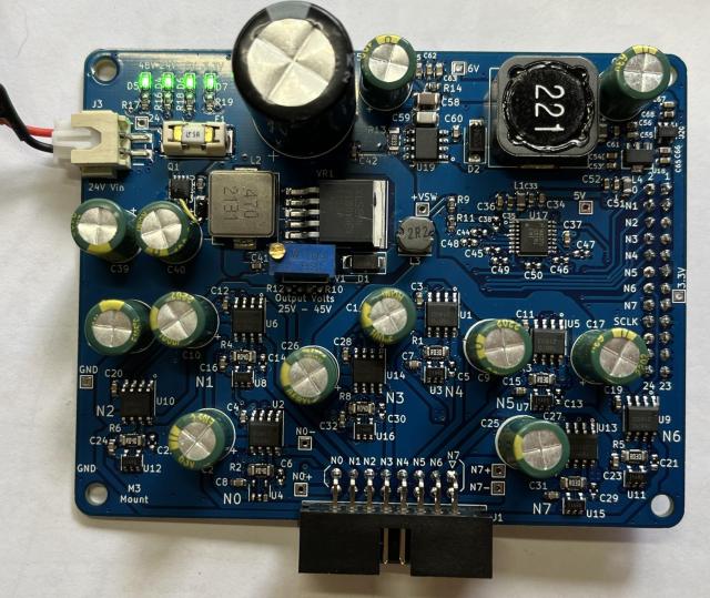
The 2nd version PCB's arrived last week, and I jumped in and assembled them and I think they came out looking really nice:

Controller Front:
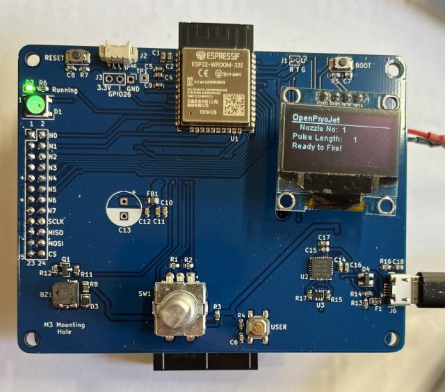
OPJ-Controller_V0.6_sml.jpg
OPJ-Controller_V0.6_sml.jpg (58.25 KiB) Viewed 12374 times
Driver Front:
OPJ-Driver_V0.6_sml.jpg
OPJ-Driver_V0.6_sml.jpg (75.52 KiB) Viewed 12374 times
So the changes between the V0.5 and V0.6 PCB versions are mainly that it now has individual ADC monitoring of each nozzle current, and a cleaner ADC voltage reference and 3.3V lines. The only mistake was that I used a 0805 footprint for a 12V zener diode and instead I purchased a SOD-123 sized zener. This is easily fixed with a short 6mm bit of bodge wire.

It took a day or so before I could get my code to read the ADC128S102 ADC SPI based IC. I had never written SPI code before and was a bit daunted by it, but in the end it turned out to be very easy, and I am getting around 25u Second read time for a 12bit value.

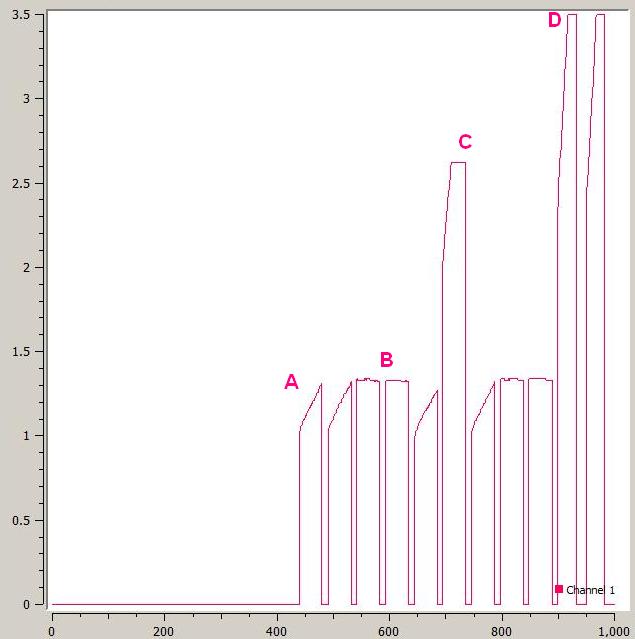
Here are some labelled plots (via SerialPlot), of various firings:
ADC_Plots.jpg
ADC_Plots.jpg (26.42 KiB) Viewed 12374 times
A: is two firings of a ~39 ohm filament. You can see the current rises over time.
B: two firings of a 22 ohm resistor
C: a filament being fired but ADC cuttings out/limiting (0.04 ohm sense resistor) the readings.
D: I then moved to using a Nozzle with a smaller 0.03 ohm sense resistor and got these two plots. They are being limited due to reaching the motor driver current limit.

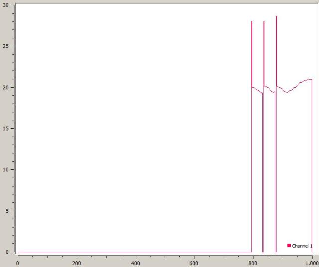
So, all is good, but then late one night, I had a go at trying to monitor the motor driver voltage and produced this horrid graph:
Bad_ADC.jpg
Bad_ADC.jpg (14.37 KiB) Viewed 12374 times
To me, it looked like there was a huge voltage sag when the Nozzle was filing, going from near 30V down to 19V! I didn't sleep well that night. Later the next day though, I re-checked the circuit and it all looked ok. I put together a voltage divider and checked my bench power supply to make sure it was supplying the correct current, and it could put out a max. of 26V at 4A, so that sounded ok. Late that evening, I delved into the code and sure enough, found the large pulse was a buffer over run which was quickly fixed (what was I thinking, why did write the code that way?). The last code error that was giving me the 19V readings was me not doing the maths correctly. Once I fixed that, I was getting a solid 30 odd volts.

This last graph is a total of 6000u seconds, with the hand drawn green trigger pulse showing approximately when the nozzle is firing for 1000u seconds. It kind of looks ok. Previously oscilloscope readings show that there is a bit of a sag, but maybe only 1V or so, which sounds ok to me. More on this in a later post.
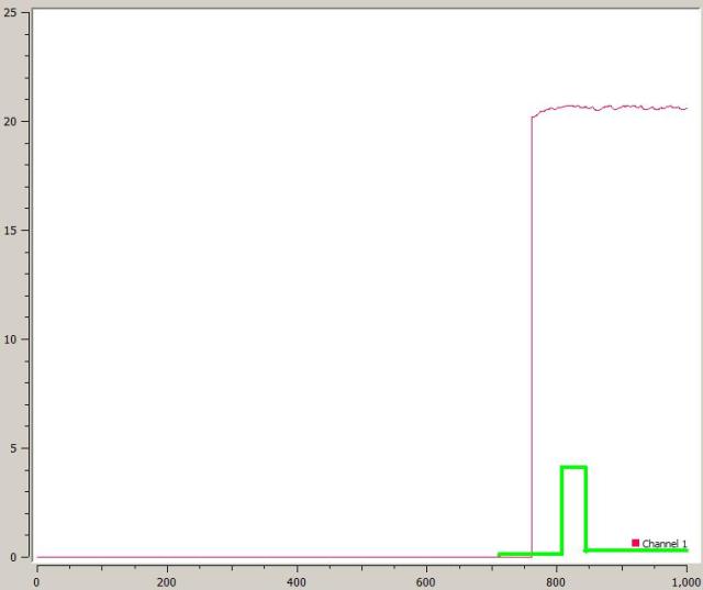
Good_ADC.jpg
Good_ADC.jpg (12.34 KiB) Viewed 12374 times
I have already drawn up a new schematic and laid out the PCB with the following small changes:

* fixed the Zener footprint
* added a power switch, which switches a MOSFET on/off. Handy when doing Dev work
* added a 5V reference IC to give a more precession voltage for the ADC
* added an extra resistor to the 6V DC-DC feed back divider, so the output voltage can be better tuned
* the next version V0.7 will be done in hot Red solder mask :)

parkview
Guru Maker
Posts: 603
Joined: Tue Jun 24, 2014 8:25 pm
Location: Busselton
Contact:

Re: Open-PyroJet a 3D Metal/Ceramic Printer

Post by parkview » Fri Aug 26, 2022 5:33 pm

Version 0.7 of both PCB's have been assembled and tested. With only a few small changes in the design - just to make it to work better:
OPJ_Driver-Board_V0.7.jpg
OPJ_Driver-Board_V0.7.jpg (140.15 KiB) Viewed 11715 times
Of course, as per usual, once I have a break with a project and start working and thinking about it again, I usually come up with possible enhancements. In this case, I think that if I add i2C back onto the driver board, I could add a i2C based 4 port GPIO Port expander IC. This would allow me to setup four different voltage dividers on the feedback circuit for the 24V DC-DC switching boost convertor. This would then give some kind of digital control over the output voltage, which would be really cool. At the moment the user has to manually adjust the pot for the required output voltage: 25V to 44V.

Post Reply