I saw these nice looking i2C based rotary encoders on Adafruit:
https://www.adafruit.com/product/4964 and thought it might be fun to make one based around a ESP32-Pico MCU. This MCU includes a crystal built into it and some flash memory. I am not using the WiFi section for this project. It is programmed via an external UART board, so I only needed the Rx/Tx pins broken out via a 1.27mm female connector. The initial version also includes an OLED screen connector, but maybe that was a bit of overkill for this project.
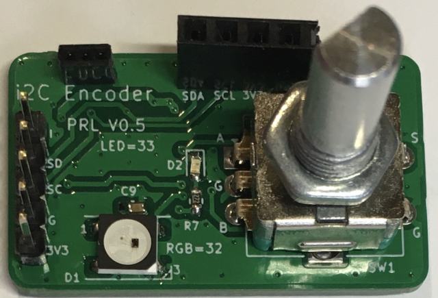
- i2c-encoder-front.jpg (40.73 KiB) Viewed 16208 times
The board contains the Pico MCU, a single WS2812 RGB LED and a green power LED and a push switched rotary encoder. As you rotate the encoder, the RGB LED changes colour - kind of a visual feedback that something is happening. I have coded it so that the rotations range from 1 to 255, The idea is that the current number will be available via the i2C bus. This board acts as a slave i2C sensor component. Pressing the encoder switch, will raise the Interrupt pin HIGH. The next i2C read of the encoder value will clear the interrupt pin back to a LOW.
The boards base i2C slave address is currently set to 0x70, and I have provided 3 address solder pads, so you can have up to 8 of these boards connected on one i2C channel.
The output connector pins are:
+3.3V
GND
SCK
SDA
INT
The back side has the ESP32-Pico MCU:
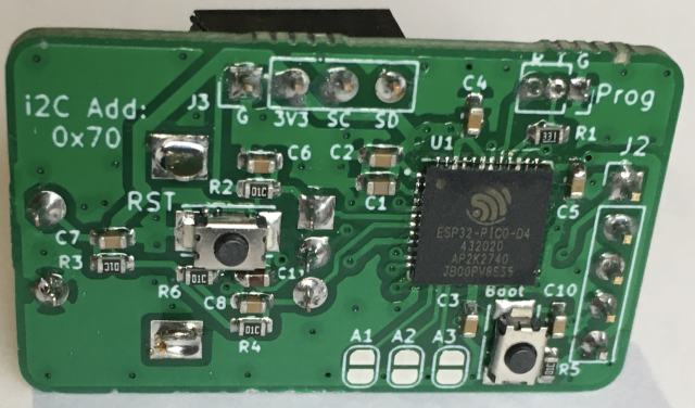
- i2c-encoder-back.jpg (43.04 KiB) Viewed 16208 times
This is a 3.3V sensor only, so you can't use it with a 5V based board like the Arduino Uno or Nano etc. Well, you could use it, but you would need a 3.3V to 5V data translator board.