For this version, I ditched the ESP32-Pico MCU, and used the ESP32-S3-Mini. This comes with a built in UART, so it saves me having to add on a CP2102 UART and the cost of it. While it's easier to mount correctly, it's still a bit tricky, in that the pads are all hidden underneath, so the fix for an open circuit pad connection, is to use a different one (see all the small spare square pads on either side), or hot plate it off and back on again. Here is the final product:
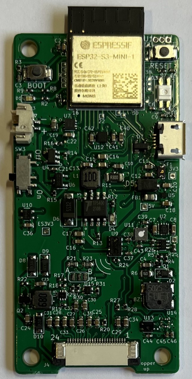
- Name-Badge_v0.9.jpg (233.53 KiB) Viewed 19823 times
I did have the ePaper CS pin open, so I fixed that with a bodge wire to a spare pin close by. It was easier than hot plating it on/off again. I spent two days troubleshooting the ePaper and then the i2C bus. Both wouldn't work. Then I noticed that with a Logic Analyzer attached, that if I did a simple i2C bus scan that the i2C bus worked (using a different code base). However, it failed to work with my normal code that had worked with v0.8 PCB. Also, the ePaper screen only showed noise, no text. Turns out I was calling the i2C bus setup BEFORE the SPI bus setup. Normally I don't think the sequence should matter, however if I reversed the setups, then both worked ok. Yay!
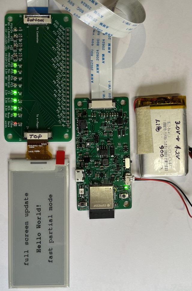
- Name-Badge-v0.9_Testing.jpg (159.91 KiB) Viewed 19823 times
I have to say, having the ePaper breakout PCB was very handy, as I can see the state of the SPI bus and voltages all with a quick glance. Invaluable!
I wrote a new code base to test all the sensors and ePaper out. This will help me in future versions of the PCB and in quickly verifying it all works ok. One thing I noticed was that it's impracticable to use the SGP30 VoC/CO2 sensor on a battery powered PCB, as it needs to run for 12 hours to establish a baseline calibration. Also it doesn't like having the power turned on/off a lot.
One thing I did get wrong was the foot print of the SK6812. This was a very late minute addition and I was running late for a meeting, so I didn't check it well enough and got the footprint back to front. It does work, but on this board it has to face upwards, whereas it should shine through the PCB and ePaper display.
So, on with the next version. This one has the SGP30 VOC/CO2 sensor and associated circuitry has been removed. The light sensor has been moved to the PCB edge. The SK6812 RGB LED footprint has been fixed. The design was uploaded today, so might be back by mid July?