80W Chinese Laser Cutter Commissioning
Posted: Mon Nov 21, 2016 12:12 pm
New 80W Chinese Laser cutter arrived last week from eBay...took approximately a week and a half to be shipped from Sydney, Jo my partner purchased it for her business and (cough cough) other maker activities  . So yesterday I got a chance to set things up and commission it.
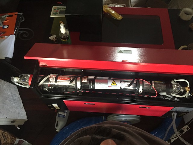
This thing was very well packed and the nice courier actually unpacked it and helped her move it inside the house where its temporary home is until new Shed is build.
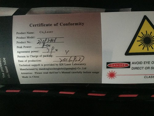
Looks like installed tube is actually rated at 70W with peak power at 80W . Not really surprised with this as it happened to Paul with his 60W and I was sort of expecting it. I'll decide if its worth pursuing further with seller as probably not worth the hassle, although I haven't given any feedback as yet so still may have some leverage.
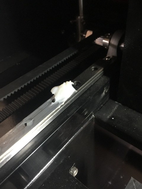
First thing was to remove all the grease on the rails which was layed on pretty thick. There was also quite a bit of swarf floating around in the bottom of the various compartments, sop removed all that too.
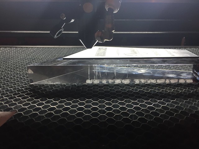
All peripheral equipment was hooked up and tested i.e. water pump for tube cooling, air assist and extraction fan then powered up. Language is in Chinese I know Paul sent me instructions of what he did to get english menu, but I didn't have my computer handy so just browsed through each menu until I could read english and enabled it. This worked and now all readable and could perform motion tests which were all straight forward and all worked as it should.
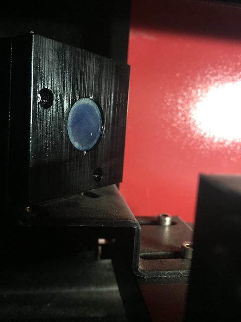
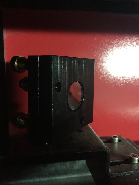
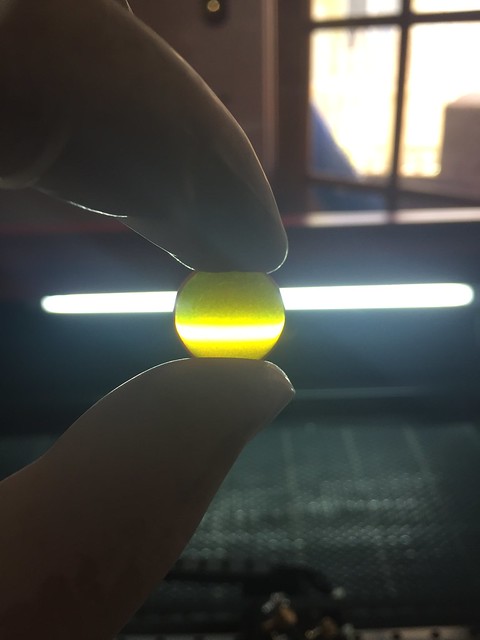
Next was cleaning the optics, all optics were in bad need of cleaning, from the photos you can see the initial state of them before and after cleaning with a bit of isopropyl on cotton buds.
2nd Mirror Before:
After:
Focal Lens Before:
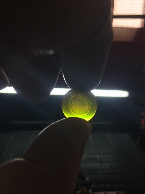
After:
The rest were much like these so won't bore you with their pictures.
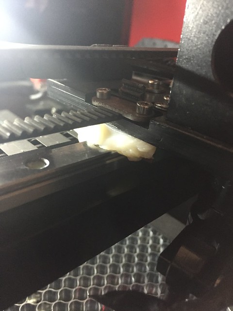
Once optics cleaned now the fun part of alignment, I suspected that these should be factory aligned....how wrong I was. The did have it roughly aligned, even had the 1st mirror stand in back to front so I couldn't adjust mirror height easily as you can see in the first picture how far off the initial alignment was like on the first mirror, well it was a similar story on the rest.
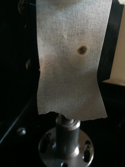
Alignment procedure was to stick some masking tape over the optics as the beam is not visible and set power to lowest it can fire, in my case 12% seemed to work pretty well. I quickly learned after the first couple of test fires I need a few layers of tape as I had to clean the optics again where it burnt through with a single ms pulse at 12%.
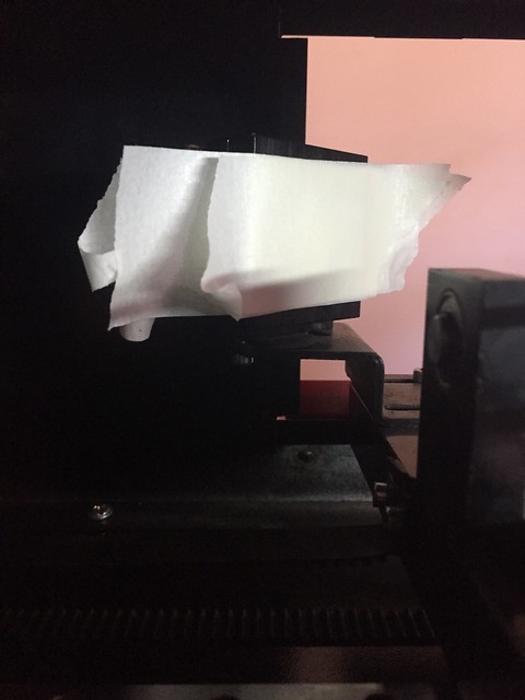
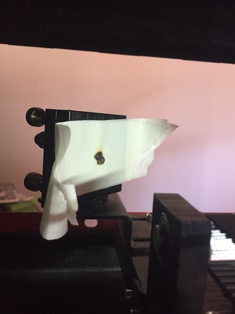
From the burn mark you can then see where the beam is in relation to the optics and so mirror is adjusted accordingly to get beam fairly central to the first mirror.
Alignment as shipped 1st Mirror
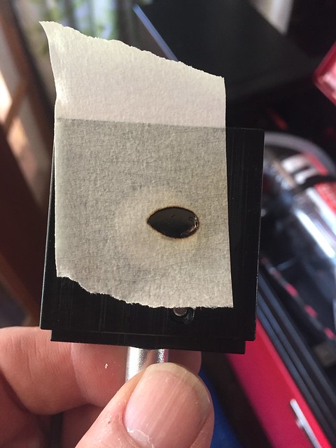
Adjusted
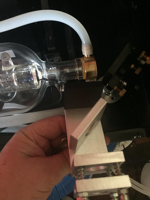
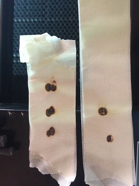
Then same process for the next two mirrors except the alignment needs to be performed on each of the Axis both near and far, i.e. move the Y Axis closest to the tube, do test fire and then move Y Axis to its extent and do another test fire, then make adjustment then rinse and repeat. This process ensures the beam is perpendicular along each axis under alignment. Here you can see the progressive alignment in the mirrors adjustments of the 2nd mirror in relation to the 3rd mirror aka Moving Head (X-Axis).
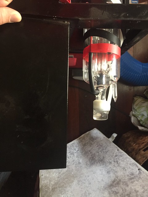
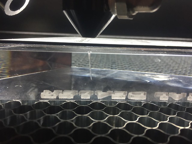
Final Mirror on the X Axis was the hardest as for the life of me I couldn't get it aligned and central to the mirror. This mirror is the moving head mirror which directs the beam to the focal lens and out the nozzle onto the workpiece. I aligned as best as I could albeit a little high and proceeded to test nozzle alignment which was central to the exit nozzle so I though was good to go, however I found that the beam hitting the work piece was skewed to the right.....i.e. if you sit facing the head the beam should be hitting right below it along the beam axis, well this was to the right about 5mm so I tried to manually adjust the head mirror, I managed to pull it back under but from redoing a nozzle test I found it to be hitting the side of the nozzle and more than likely reducing exit power considerable. This skew is being caused by the beam not hitting the focal lens centrally and hence the optics will bend the light.
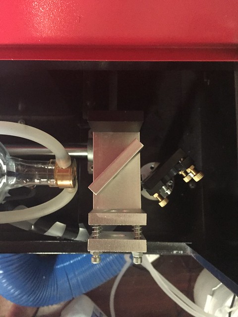
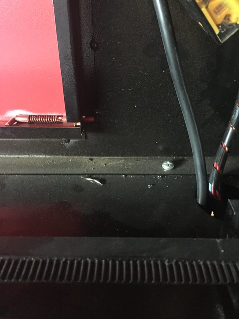
After a lot of head scratching I reviewed the entire optical path to see how it could be adjusted as it looked like the entire beam needed to go down so that I could get it central on the head mirror (was currently high) My answer to the problem appears in the form of a lock nut below the Laser Tube. I thought Id give it a go and loosen then adjust it down. success the beam dropped, After checking all the path alignment again all was good except for the exit nozzle was off, this made sense as is now hitting optics fairly centrally and so after a small head mirror adjustment I my beam was central and hitting directly under the head!!!
I will post some more photos of the my test fires and alignment shortly to show how I could see the beam path of my cuts through this adjustment process.
Anyway very happy with the initial results and definitely shows that the Chinese laser cutters need a fire bit of cleaning and adjustment before putting into service.
This thing was very well packed and the nice courier actually unpacked it and helped her move it inside the house where its temporary home is until new Shed is build.
Looks like installed tube is actually rated at 70W with peak power at 80W . Not really surprised with this as it happened to Paul with his 60W and I was sort of expecting it. I'll decide if its worth pursuing further with seller as probably not worth the hassle, although I haven't given any feedback as yet so still may have some leverage.
First thing was to remove all the grease on the rails which was layed on pretty thick. There was also quite a bit of swarf floating around in the bottom of the various compartments, sop removed all that too.
All peripheral equipment was hooked up and tested i.e. water pump for tube cooling, air assist and extraction fan then powered up. Language is in Chinese I know Paul sent me instructions of what he did to get english menu, but I didn't have my computer handy so just browsed through each menu until I could read english and enabled it. This worked and now all readable and could perform motion tests which were all straight forward and all worked as it should.
Next was cleaning the optics, all optics were in bad need of cleaning, from the photos you can see the initial state of them before and after cleaning with a bit of isopropyl on cotton buds.
2nd Mirror Before:
After:
Focal Lens Before:
After:
The rest were much like these so won't bore you with their pictures.
Once optics cleaned now the fun part of alignment, I suspected that these should be factory aligned....how wrong I was. The did have it roughly aligned, even had the 1st mirror stand in back to front so I couldn't adjust mirror height easily as you can see in the first picture how far off the initial alignment was like on the first mirror, well it was a similar story on the rest.
Alignment procedure was to stick some masking tape over the optics as the beam is not visible and set power to lowest it can fire, in my case 12% seemed to work pretty well. I quickly learned after the first couple of test fires I need a few layers of tape as I had to clean the optics again where it burnt through with a single ms pulse at 12%.
From the burn mark you can then see where the beam is in relation to the optics and so mirror is adjusted accordingly to get beam fairly central to the first mirror.
Alignment as shipped 1st Mirror
Adjusted
Then same process for the next two mirrors except the alignment needs to be performed on each of the Axis both near and far, i.e. move the Y Axis closest to the tube, do test fire and then move Y Axis to its extent and do another test fire, then make adjustment then rinse and repeat. This process ensures the beam is perpendicular along each axis under alignment. Here you can see the progressive alignment in the mirrors adjustments of the 2nd mirror in relation to the 3rd mirror aka Moving Head (X-Axis).
Final Mirror on the X Axis was the hardest as for the life of me I couldn't get it aligned and central to the mirror. This mirror is the moving head mirror which directs the beam to the focal lens and out the nozzle onto the workpiece. I aligned as best as I could albeit a little high and proceeded to test nozzle alignment which was central to the exit nozzle so I though was good to go, however I found that the beam hitting the work piece was skewed to the right.....i.e. if you sit facing the head the beam should be hitting right below it along the beam axis, well this was to the right about 5mm so I tried to manually adjust the head mirror, I managed to pull it back under but from redoing a nozzle test I found it to be hitting the side of the nozzle and more than likely reducing exit power considerable. This skew is being caused by the beam not hitting the focal lens centrally and hence the optics will bend the light.
After a lot of head scratching I reviewed the entire optical path to see how it could be adjusted as it looked like the entire beam needed to go down so that I could get it central on the head mirror (was currently high) My answer to the problem appears in the form of a lock nut below the Laser Tube. I thought Id give it a go and loosen then adjust it down. success the beam dropped, After checking all the path alignment again all was good except for the exit nozzle was off, this made sense as is now hitting optics fairly centrally and so after a small head mirror adjustment I my beam was central and hitting directly under the head!!!
I will post some more photos of the my test fires and alignment shortly to show how I could see the beam path of my cuts through this adjustment process.
Anyway very happy with the initial results and definitely shows that the Chinese laser cutters need a fire bit of cleaning and adjustment before putting into service.